Exmark eXmark Ultra VAC Lazer Z User Manual
Browse online or download User Manual for Lawnmowers Exmark eXmark Ultra VAC Lazer Z. Exmark eXmark Ultra VAC Lazer Z User's Manual
- Page / 44
- Table of contents
- TROUBLESHOOTING
- BOOKMARKS
- W ARNING 2
- HEALTH WARNING 2
- GASOLINE 2
- EXMARK PARTS PLUS 3
- PROGRAM 3
- OPERATOR'S MANUAL 4
- TABLE OF CONTENTS 5
- 1. SAFETY 6
- ATTENTION! BECOME ALERT! 6
- YOUR SAFETY IS INVOLVED! 6
- 1.4 OPERATION 7
- 1.5 MAINTENANCE AND STORAGE 9
- 1.6 RIDING ATTACHMENTS 9
- 1.7 SAFETY SIGNS 9
- 2. SPECIFICATIONS 11
- 3. ASSEMBLY INSTRUCTIONS 13
- Drive Lever 18
- Neutral Lock/Park Brake Latch 18
- Drive Linkage 18
- Clevis Pin 18
- 4. OPERATION INSTRUCTIONS 20
- 4.2 PRE-START 22
- 4.3 OPERATING INSTRUCTIONS 23
- 4.4 TRANSPORTING 25
- 5.1 PERIODIC MAINTENANCE 25
- LUBRICATION CHART 29
- SPRAY LUBRICANT CHART 30
- 5.2 ADJUSTMENTS 31
- 48” Deck 34
- Used For 34
- Reference Only 34
- 6. TROUBLE SHOOTING 37
- ENGINE TROUBLESHOOTING 38
- 8. WIRING DIAGRAMS 39
- 9. WARRANTY 40
- SERVICE RECORD 42
- FOLD ALONG APPROPRIATE LINE 43
- MFG. CO. INC 44
Summary of Contents
- 5 -PART NO. 323550LOCATION: Upper Handles(Both Sides)PART NO. 403005LOCATION: Front Cornersof DeckPART NO. 303508LOCATION: Right Rear Cornerof Deck8
- 6 -2. SPECIFICATIONS 2.1 MODEL NUMBER:2.2 ENGINE2.2.1 Engine Specifications: See yourengine owner's manual.2.2.2 RPM (No Load): 3600 rpm2.3
- 7 -2.3.3 Fuel Filter: Replaceable in-line2.3.4 Fuel Shut Off Valve: in-line, 1/4 turn 2.4 SAFETY INTERLOCK SYSTEMOperator must have the transmission
- 8 -2.9.6 Cutting Height: Adjusts in 1/4" (.63 cm) or smallerincrements by various adjustments of caster spacers,blade spacers and axle height,
- 9 -3.5 Install casters to front of deck using appropriatehardware from the bolt bag (eight 3/8 x 3/4" boltsand eight 3/8" whizlock nuts);
- 10 -FIG. 2UPPER HANDLEHEIGHT ADJUSTMENT 3.8.1 Attach throttle cable to engine.For Kohler, Kawasaki, and B&S 10.5 hp Engines with "positi
- 11 -FIG 4KAWASAKI SPEED CONTROL(THROTTLE CABLE HOOK-UP)FIG 5B&S 10.5 hp SPEED CONTROL(THROTTLE CABLE HOOK-UP)d) Pull cable upward (rearward for
- 12 -For B&S 8.5 hp Engines,a) Position the throttle control lever (on console)1/8" from the lower end of the slot. Route the throttle cable
- 13 -FIG. 7THIS CLEARANCE SHOULD BE EQUAL FIG. 6 SHIFTER LEVER TO TRANSMISSION FIG. 8THIS CLEARANCE SHOULD BE EQUAL 3.8.5
- 14 -FIG. 10NEUTRAL LOCKLEVER CLEARANCENOTE: Neutral lock/park brake latch clearance should be checked when there is a slight upward force placed on
i!W ARNING!WARNING...!CAUTIONThe engine exhaust from this product contains chemicals known to the State ofCalifornia to cause cancer, birth defects,or
- 15 - 3.8.8 Route the long, unattached wiring harness lead up the left hand side of the handle and connect the two leads, in any order, to the ope
- 16 -FIG. 12DRIVE LEVER, NEUTRAL LOCK/PARK BRAKE LATCH OPERATION4.1.4 Operator Presence Control (OPC) Levers:Located on the upper handle assembly dir
- 17 -a detent at the "idle" position, continuing rearward past this detent will shut off the engine.B&S 8.5 hp Engines:For the B&S
- 18 -••••If fuel is spilled, DO NOT attempt to start the engine.Move away from the spill and avoid creating any sourceof ignition until fuel vapors h
- 19 - Close fuel shut-off valve if machine will not be used for a few days; when parking inside a building; or when transporting the unit.4.3.4 Dr
- 20 - 4.4 TRANSPORTING••••If loading with ramps, be sure rampsare properly supported and strongenough to support the unit.••••If necessary, use ass
- 21 -5.1.2 Clean engine air cooling system.Service Interval: See Engine Owner's Manuala) Stop engine and remove spark plug wire(s).b) Clean all
- 22 -either the mower blades are engaged, or the transmission shifter lever is not in neutral and the operator removes both hands from the handles, t
- 23 -engines). Clean around oil filter and unscrew filter to remove. Before the new filter is installed, apply a thincoating of oil on the surface of
- 24 -5.1.11 Inspect belt wear. Service Interval: 40 hrs.a) Stop engine and remove spark plug wire(s).b) Remove the cutter deck belt shield to check
iiEXMARK PARTS PLUS PROGRAMEFFECTIVE DATE: September 1, 1995ProgramIf your Exmark dealer does not have the Exmark part in stock,Exmark will get t
- 25 -c) Replace 5-speed gearbox grease yearly. Use 18 oz. OfPeerless grease (Part No. 788067). See Section 5.1.10.d) Lubricate pivot points with a s
- 26 -5.1.19 An anti-seize compound is used on the blade drive pulleyhub, located on the engine PTO shaft (this allows forease of removal of the pulle
- 27 -Refer to the charts and illustrations on the following pages to properly adjust for desired cutting height. FIG. 14
- 28 - NOTE: The axle positions are in 1/2" increments and the large caster spacers are 1/2" thick. Therefore, by adjusting the same number
- 29 -5.2.4 Wheel drive belts and scrapers.a) If wheel traction appears to be slipping, drive lever rods may be touching bottom of neutral lock/park
- 30 -5.2.6 Secondary belt (48" only).a) Stop engine and remove spark plug wire(s).b) The secondary drive belt is adjusted via the belt tension
- 31 -turn setscrew all the way in then back out 1-1/2 turns.IMPORTANT:Screwing setscrew in too far will prevent the transmission from shifting.5.2.1
- 32 -6. TROUBLE SHOOTING6.1 MOWER PULLING LEFT OR RIGHT.a) Check idler arm pulleys and drive sheaves for mud and/or grass buildup. Check for proper
- 33 -NOTE: After carefully checking the previous steps, attempt to start the engine. If it does not start, contact your authorized Exmark service dea
- 34 -8. WIRING DIAGRAMS
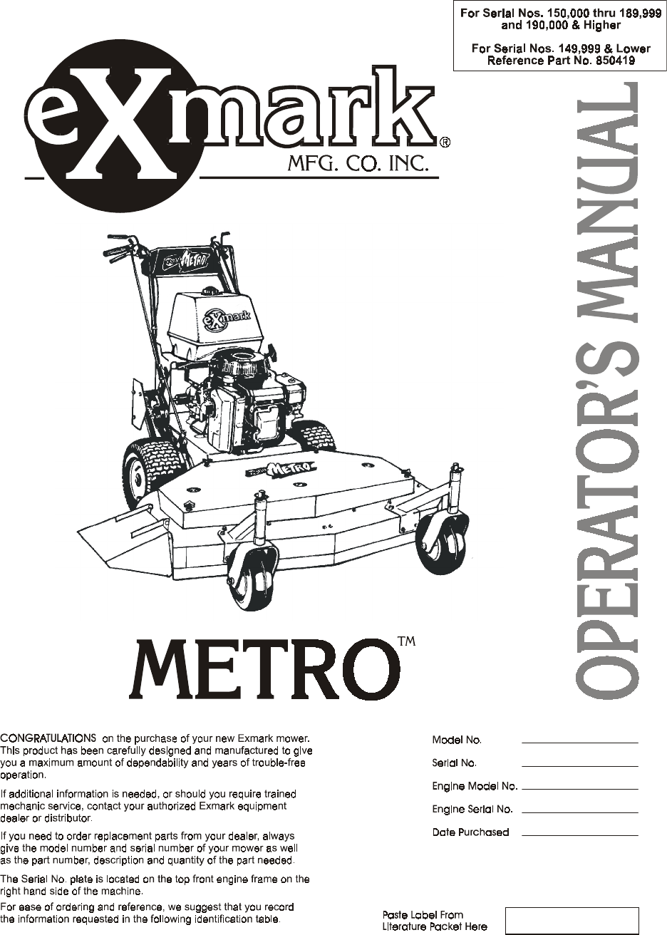
iiiCONGRATULATIONS on the purchase of your Exmark Mower. Thisproduct has been carefully designed and manufactured to give you amaximum amount of depen
- 35 -9. WARRANTYLimited Warranty Exmark Commercial Turf Equipment Exmark Mfg. Co. Inc.("Exmark") warrants on the terms and conditions herei
- 36 -instructions provided by Exmark; (vi) repair or replacement arising as aresult of any operation from turf equipment that has been altered ormod
- 37 -SERVICE RECORD Date Description of Work Done Service Done By
- 38 -THIS IS A 15° SLOPETHIS IS A 10° SLOPETHIS IS A 5° SLOPEALIGN THIS EDGE WITH A VERTICAL SURFACE(TREE, BUILDING, FENCE POST, POLE ETC.)EXAMPLE: C
SEE EXMARK’S COMPLETELINE OF PRODUCTS FOR TURF CARELAZER Z™LAZER Z™ HPEXPLORER®TURF RANGER®TURF TRACER®TURF TRACER® HPVIKING HYDROMETRO™METRO™ HPSELF
ivTABLE OF CONTENTS1. SAFETY PAGE1.1 Safety Alert Symbol ...11.2 Training ...11
- 1 -1. SAFETY1.1 SAFETY ALERT SYMBOLTHIS SAFETY ALERT SYMBOL IS USED BOTH IN THIS MANUAL AND ONTHE MACHINE TO IDENTIFY IMPORTANT SAFETY MESSAGES WH
- 2 -••••Fuel is Highly Flammable. DO NOT smokewhile refueling. Refuel only in a wellventilated area, or refuel outdoors.••••Store fuel in containers
- 3 -1.4.9 Start the engine carefully with feet well away from the blades.1.4.10 Keep hands, feet and clothing away from rotating partswhile the mower
- 4 -1.5 MAINTENANCE AND STORAGE1.5.1 For engine maintenance, follow the engine manufacturer'srecommendations precisely as stated in the engine m
Related products and manuals for Lawnmowers Exmark eXmark Ultra VAC Lazer Z
 (44 pages)
(32 pages)
(40 pages)
(16 pages)
(48 pages)
(44 pages)
(24 pages)
(24 pages)
(36 pages)
(48 pages)
(44 pages)
(48 pages)
(52 pages)
(40 pages)
(44 pages)
(32 pages)
(40 pages)
(16 pages)
(48 pages)
(44 pages)
(24 pages)
(24 pages)
(36 pages)
(48 pages)
(44 pages)
(48 pages)
(52 pages)
(40 pages)
© 2020, manymanuals.com. All rights reserved. | 1.322 s |
 Manymanuals.com
 Manymanuals.de
 Manymanuals.fr
 Manymanuals.it
 Manymanuals.pl
 Manymanuals.cz
 Manymanuals.es
 Manymanuals-pt.com
Comments to this Manuals